Select brick and press escape and give it a name patch and specify the coordinates as shown in the fig. Now to design the patch, come back to the front face and align the local coordinate system to that face. Again select the face and select extrude function from the toolbar. Select WCS and select align WCS with selected face. To create the ground plane for the antenna, rotate the substrate using the rotate icon given at the top. Select the material as FR-4 from the material library. Specify the height of the substrate h along the positive W axis. So give half of it along negative axis and half of it along positive axis.( Umin = -W & Umax = W) The same way specify Vmin as –L & Vmax as L. To create the substrate, select brick and press escape key. You can design antennas for your specifications as well.) After completing the parameter specifications, turn on the local coordinate system from WCS menu as shown below.

(note: since this is for simulation purpose we are giving these values whereas the industrial standards for fabrication will vary) *(Also note that these values are given for the specified frequency to get the results shown here.

Fi=12.5, Gpf=1, the thickness of the substrate h=4.5 and the thickness of the copper layer mt=0.1mm. Before starting to design, specify the parameters u got from the theoretical design as shown below. Give size as 100, width as 10 and change the snap width to 0.01 as shown below. Go to edit menu and select the working plane properties.

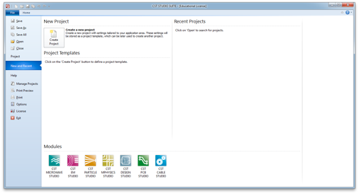
Since Microstrip patch antenna is a planar antenna select Antenna planar in the template. Now launch CST studio and select MicroWave Studio and press OK. The design formula as well as the resonant frequency for which the antenna is designed is given in the fig. Before going to the software environment, please complete your theoretical design calculations for your specifications as shown in the fig below. Design of a Microstrip patch antenna using CST MicroWave Studio


 0 kommentar(er)
